Variable frequency drive systems save energy. But they also create two problems. High harmonics and common mode voltage. Ordinary power cables cannot suppress this interference. This leads to early insulation breakdown in the motor. Bearings get damaged by electrical erosion. Nearby instruments give false signals.
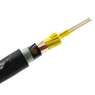
Our Vfd Motor Cable is a VFD cable. Let me rephrase. Our Vfd Motor Cable is a VFD special compound shielded cable. Its voltage rating is 0.6/1kV. It is made to connect the VFD to the VFD motor. It effectively reduces electromagnetic radiation. It also reduces ground potential rise.
We use a 3+3 core arrangement. That means three main phase cores and three neutral cores evenly and symmetrically arranged. This structure effectively cancels zero sequence harmonic flux. It prevents neutral point drift.
The shielding layer is a composite structure. Outside the stranded cable core, we first do copper wire winding shielding. Coverage is 90% or more. Then we wrap soft copper tape. Overlap rate is 15% or more. The copper wire winding provides a low DC resistance grounding path. The copper tape wrap provides 100% high frequency electric field shielding.
The insulation is XLPE. The temperature rating is 90°C. It can handle the high voltage spikes from the VFD output. The sheath is flame retardant PVC.
The copper wire plus copper tape composite structure gives the cable a transfer impedance as low as 50mΩ/m at 30MHz. This means the high frequency common mode current from the VFD is quickly absorbed by the shielding layer. Then it goes into the ground. Radiation to the outside is greatly reduced.
The symmetrical 3+3 structure and low impedance shielding layer effectively balance the three phase voltage. It reduces the common mode voltage on the motor bearing to less than one fifth of an unshielded cable. The motor bearing life is significantly extended.
The conductor working temperature is 90°C. The minimum bend radius is 15 times the cable outer diameter. VFD cables have stricter bend radius requirements because of their complex structure.
The shielding layer must be reliably grounded at both ends. This ensures the high frequency interference current has the shortest path. If grounded at only one end, the high frequency impedance increases sharply. The shielding effect is lost.
Standard product lead time depends on quantity. We try our best to meet customer needs. The same goes for custom products. Monthly production capacity depends on the specifications. Different models have different output.
Technical Data Table
|
Parameter |
Value |
|
Product Name |
Vfd Motor Cable |
|
Conductor |
Copper |
|
Core Arrangement |
3+3 symmetrical |
|
Insulation |
XLPE |
|
Shielding |
Copper wire winding (90% coverage) + copper tape wrap (15% overlap) |
|
Sheath |
Flame retardant PVC |
|
Voltage Rating |
0.6/1kV |
|
Normal Working Temp |
90°C |
|
Transfer Impedance |
≤50mΩ/m at 30MHz |
|
Min Bend Radius |
15 x outer diameter |
|
Best Application |
Connecting VFD to VFD motor |
Hot Tags: vfd motor cable, China vfd motor cable manufacturers, Flexible Vfd Cable, Vfd Motor Cable, Flexible Inverter Cable Flame Retardant, Variable Speed Drive Cable, variable frequency drive cable, Dual Shielded Inverter Flexible Cable